


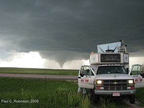
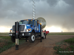
CSWR's Doppler on Wheels (DOW) network consists of three mobile doppler radar trucks, DOW 6, DOW 7 and the Rapid Scan DOW (DOW 5).
Many of the important meteorological phenomena (such as tornadoes, hurricanes, microbursts, dust devils, etc.) occur infrequently and/or very near the ground. These are difficult to measure with traditional stationary meteorological radars, due to temporal and/or spatial limitations. Additionally, many interesting physical processes occur at subkilometer scales, but the ranges between the phenomena of interest and the stationary radars are almost always quite large. This results in finescale (subkilometer) structures being unresolvable due to beam spreading between stationary radars and the targets. Near-ground (<300 m AGL) structures are often undetectable due to the masking of the transmitted beam by topography and obstructions, vertical beam spreading, and earth curvature. Finally, these phenomena frequently occur on timescales of seconds to minutes and thus are sampled poorly by typical surveillance radar scanning strategies. Thus, there was a need for finescale observations of these phenomena in order to better understand the mechanisms involved in their formation and maintenance.
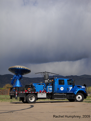
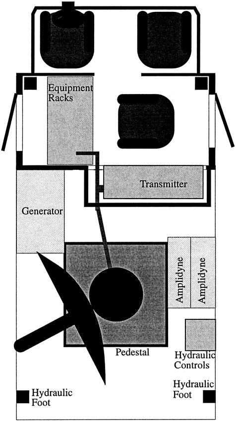
The first generation of DOWs (Figure 1) were mounted on a modified medium-sized General Motors Chevrolet light duty panel truck (5.4-m length) provided by the National Severe Storms Laboratory (NSSL). Hydraulic outriggers allow for leveling and stability of the 4900-kg system. The maximum height of the antenna dish when pointed rearward for transport is 3.38 m (11' 1") above ground level (AGL) permitting travel on most roads and allowing easy loading onto cargo aircraft for rapid deployment to remote locations. When pointing vertically, the feedhorn extends to 3.68 m (12' 1") AGL, which is lower than most highway overpasses. Deployment costs are very low, mainly consisting of gasoline and operator salaries. The radar has scanned to collect data while mobile in headwinds of 40 m s-1, and it is estimated that the vehicle can sustain winds and continue data collection in winds exceeding 50 m s-1. A gasoline-fueled generator with a capacity of 9 kVA (208 V, three phase) provides power to all systems. The truck and generator proved to be somewhat underpowered and, therefore, subsequent generations of DOWs use larger, more powerful vehicles and generators.
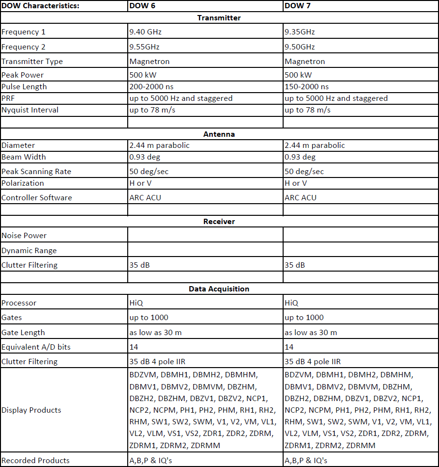
The DOW incorporates a surplus transmitter from the NCAR CP-2 radar that operates at 9.375 GHz. This transmitter has been modified to operate at a higher pulse repetition frequency (PRF), 2000 Hz, resulting in a Nyquist interval of 32 m s-1 (velocity folds at ±16 m s-1, ±48 m s-1, ±80 m s-1), which is suitable, although not optimal, for tornado studies. The pulse length has been shortened to slightly less than 0.5 µs, both to reduce the duty cycle and to permit finer-scale range measurements (75 m). Peak power output is 45 kW. Use of this relatively high power transmitter enables the DOW to achieve sensitivities very similar to that of the pre-1994 CP-2 radar. The radar characteristics, similar in several categories to the NCAR CP-2 radar, are summarized in Table 1. The transmitter was of the noncoherent magnetron type, requiring software phase locking, accomplished digitally, in order to produce Doppler velocities.
A military surplus MP61 antenna with a diameter of 1.83 m (6') was attached to a SCR-584 pedestal system (similar pedestals are used in the NCAR CP-3, CP-4, and ELDORA test bed radars), resulting in a beamwidth of 1.2°. Azimuth and elevation drive motors were capable of scanning up to 60° s-1 but were limited to 30° s-1 by the antenna controller. Since the first application of this radar was in severe weather, the rugged nature of this military pedestal system was desirable, despite the difficulties caused by its weight—estimated in excess of 1000 kg—and archaic design.
A 1.2° beamwidth provided beamwidths of 64 m at a range of 3 km. This, combined with the 500-ns pulse width described above, resulted in resolution volumes of 64 m × 64 m × 75 m, 310000 m3. This is less than 0.25% of that typically achievable with stationary radars and 4% that of airborne systems at typical ranges to tornadoes, thus providing a 25 to 400 times improvement in volumetric resolution. The narrow beamwidth and the ability to choose sites with good visibility permitted data to be retrieved to within 100 m of the ground in tornadoes.
The antenna controller for the DOW radar was implemented with a 486-class PC and a custom interface designed for utilization of the SCR-584 pedestal (Fig. 2). Antenna position is sensed by synchrotransducers that provide three phase signals to the interface. Two synchro-to-digital converters (SDCs) convert the three phase signals to weighted binary values. The binary values are converted to binary-coded decimal (BCD) using lookup tables for display. Binary position information is provided to the parallel input card in the PC.
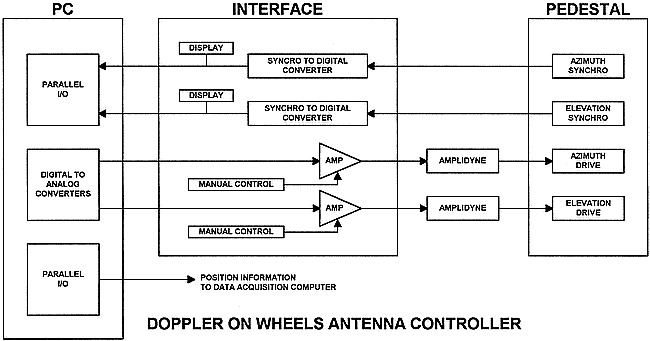
The PC’s internal 50-ms clock is used to sample the input antenna angular position values. The antenna angular position, antenna direction, and antenna rotation rate are calculated and sent to the data acquisition computer and the control program. Corrections are calculated with a predictive algorithm, and torque-limiting and antihunt features were implemented. Adjustments are output to the digital-to-analog converters (DAC) on the analog output card in the PC then to the isolation amplifiers in the interface. Analog drive circuits in the interface were designed to provide isolation, bias offset, and current drive for the field windings of the amplidynes. The original SCR-584 pedestal electronics system that was based on vacuum tube technology was not stable enough for this application.
The Doppler On Wheels (DOW) radars have been used since 1995 to study a variety of atmospheric phenomena, and as of 2010, dual-Doppler, dual-polarization, dual-frequency retrievals at 50-s intervals are also possible via DOWs 6 and 7.
Rapid evolution and small-scales are tightly linked, and since data from the DOWs suggested that observations of phenomena associated with tornadogenesis, microbursts and hurricane boundary layer wind streaks are poorly resolved by conventional scanning radars and even conventional mobile radars (due to spatial and temporal limitations, respectively), rapid-scan and mobility go hand in hand.
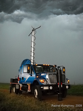
Although historically, phased array rapid-scan technologies have been prohibitively expensive, in 2001, CSWR began developing an experimental rapid-DOW, capable of scanning with a multiple beam system to collect partial volumetric data in approximately 10 seconds. Operating, the rapid-DOW incorporates a slotted waveguide array antenna, designed to produce frequency dependent beam steering. Energy from a single transmitter produces six pencil-beams, each with a distinct frequency and elevation angle, nearly simultaneously (see Figure 3 below.) The rapid mechanical azimuthal scanning results in a six-beam sweep of the sky in six seconds.

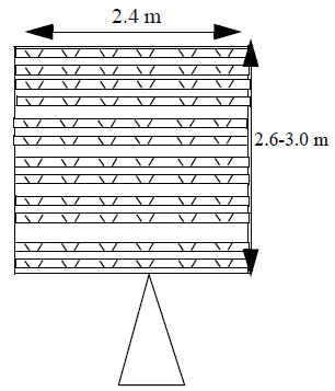
The antenna array, approximately 2.4 m on a side, consists of individual slotted waveguide elements (See Figure 4 below.) At any given frequency, the array produces a 0.9°-1.0° beam. All returned signals pass through single rotarysjoints, circulator, and amplifier and initial IF downconversion, before being split and sent to individual frequency modules (channels).
Steering is approximately .03° (MHz)-1, producing approximately 15° steering across the X-band spectrum (9.3-9.8 GHz). Pulse lengths as short as 125 ns result in negligible dispersion (8MHz effective bandwidth results in just .24°dispersion) within individual beams. Minimum frequency separations can be adjusted depending on pulselengths in order to provide channel isolation.
Returned energy from all of the beam is received simultaneously, then split and processed by individual frequency modules, and the frequency of each individual beam is independently controlled by individual synthesizers in each frequency module. By changing the frequencies of the transmitted energy, the elevation angle offsets of the individual beams can be modified, allowing elevation angle offset sets to be tailored for boundary layer or deep convective studies. The elevation angle of any beam can be changed on a integration-time-by-integrationtime basis, permitting saw-toothed or dithered scans. This permits a better matching of horizontal and vertical observation scales.
